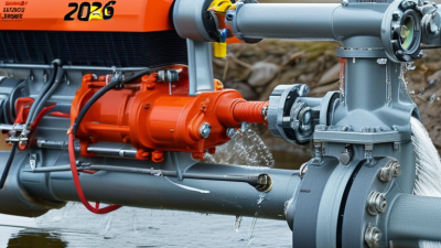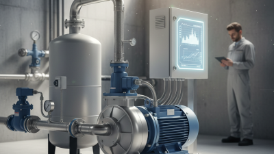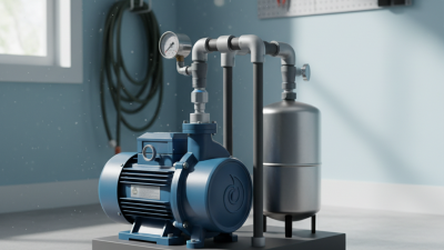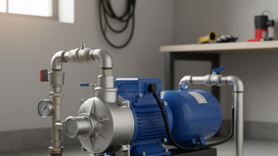
A flow jet water pump is a pressure-driven system designed to move water from a well, tank, or low-pressure source. It uses a centrifugal pump, a jet assembly, and carefully shaped water passages. Together, these parts create the pressure needed to lift water and deliver it through household pipes. The design is common in shallow-well and deep-well applications, although the correct model depends on well depth and installation conditions.
The working process is practical but easy to misunderstand. The pump pushes water through a narrow nozzle inside the jet assembly. This movement creates a pressure drop, drawing additional water into the system. The combined water stream then returns to the pump, where the impeller raises its pressure again. A pressure tank stores part of this water, helping reduce frequent motor starts. You may hear a brief hum, followed by steady pipe flow.
Small details affect performance. A leaking foot valve can allow water to drain back into the well. Air entering the suction line may cause weak pressure or repeated loss of prime. Correct pipe sizing matters too. It is not merely a plumbing detail.
However, the term flow jet water pump can describe several configurations. Some systems use a shallow-well jet assembly, while others place the injector below ground. Manufacturer instructions, measured well depth, and local water conditions should guide selection. Real installations are rarely perfect. Sand, mineral buildup, and aging seals can change results over time. Understanding these limits makes troubleshooting safer and more reliable.
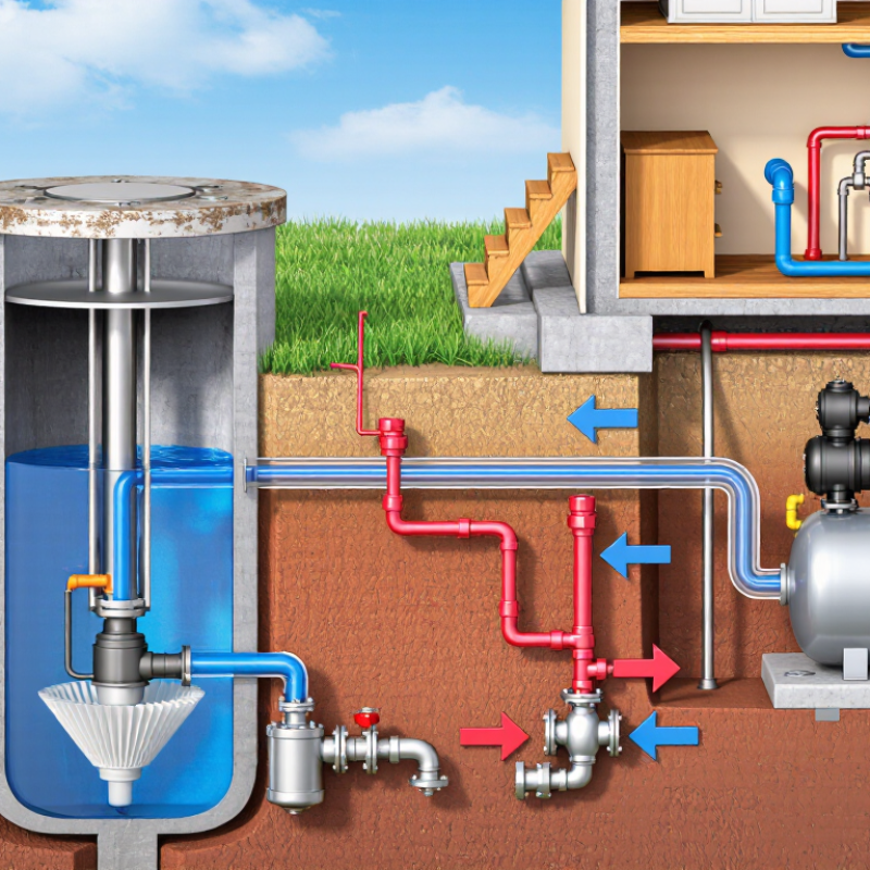
A flow jet water pump combines a centrifugal impeller with a jet assembly. The impeller spins inside the casing, adding velocity to incoming water. Its curved blades push water outward, creating pressure at the discharge. The U.S. Department of Energy reports that pumping systems may consume 25–50% of industrial facility electricity. Small hydraulic losses therefore deserve serious attention.
The venturi nozzle narrows the flow passage and accelerates water. This lower pressure draws additional water through the suction pipe. The diffuser then widens the passage gradually, converting velocity into usable pressure. A poorly aligned diffuser can create turbulence, noise, and unstable flow. I have seen clear water become cloudy after air entered through a loose suction fitting.
The check valve prevents reverse flow when the impeller stops. It protects the priming cycle and limits sudden pipe movement. However, a sticky valve can restrict flow almost like a hidden blockage. The Hydraulic Institute emphasizes matching pump performance with system resistance, rather than selecting capacity alone. That matters in real installations.
Pressure gauges help verify the pump’s operating point. Do not trust a single reading. Record suction pressure, discharge pressure, flow, and motor current together. The IEA’s Energy Efficiency 2023 report identifies motor-driven systems as major global electricity users, reinforcing the value of accurate adjustment. The anatomy looks simple. Field conditions are not.
What Is a Flow Jet Water Pump and How Does It Work?
How Water Moves: The Step-by-Step Jet-Ejector Circulation Process
A flow jet water pump uses pressure and velocity to move water through a compact circulation path. An electric motor spins an impeller inside the pump housing. The impeller pushes water outward, raising its pressure and speed. This energized water then enters a narrow jet nozzle.
Here, the real action begins. The nozzle forces water through a small opening, creating a fast-moving stream and a low-pressure zone beside it. That pressure drop draws additional water from the suction pipe. The two flows meet inside the mixing chamber, where turbulence blends them together. The mixture then enters a diffuser. Its wider passage reduces velocity and converts part of that motion into usable pressure. Water leaves through the discharge pipe, while the impeller continues feeding the jet.
The process repeats.
In practical installations, even small details affect performance. A loose suction fitting may pull air instead of water. A clogged nozzle can weaken the ejector effect. I have found that cloudy discharge water often deserves inspection, not dismissal. It may indicate air leaks, disturbed sediment, or an oversized intake opening. The pump also needs a filled casing during startup, unless its design includes a suitable priming system. Pressure readings should be checked with steady flow, because a brief peak can create a misleading impression. Real systems are rarely perfect. Careful observation remains more reliable than assuming every circulation cycle behaves identically.
A flow jet water pump uses a nozzle and venturi chamber to move water from a shallow source. The drive water passes through the nozzle at high velocity. This lowers pressure inside the chamber. Atmospheric pressure then pushes source water into the suction pipe. The two streams mix before reaching the diffuser and discharge line.
The familiar suction limit comes from atmospheric pressure. The U.S. Standard Atmosphere gives sea-level pressure near 101.3 kPa. That pressure can support a theoretical water column of about 10.3 meters. The limit is physical. It is not a pump rating. Hydraulic Institute guidance shows that vapor pressure, pipe friction, fittings, and entrance losses reduce usable suction lift. At warmer water temperatures, vapor pressure rises and the available margin becomes smaller. Cavitation may then produce noise, vibration, and unstable flow.
Field measurements often reveal a lower practical limit, commonly around 7 to 8 meters under favorable conditions. That figure is not universal. Elevation, water temperature, pipe diameter, and airtightness all matter. I have seen suction systems blamed on weak pumps when small leaks were the real problem. That assumption deserves checking. A tiny joint leak may admit air without releasing visible water. Good installation keeps the suction pipe short, fully submerged, and gently sloped toward the source. Designers should also verify net positive suction head requirements, rather than trusting the 10.3-meter figure alone.
| Data Dimension | Typical or Reference Value | Technical Explanation |
|---|---|---|
| Pump Type | Jet water pump | A centrifugal pump combined with a nozzle and venturi assembly. It uses part of the pressurized discharge water to create a low-pressure region that draws water from a source. |
| Main Energy Source | Mechanical energy from the motor | The motor drives the impeller, which raises the pressure and velocity of the water. The pressurized water then powers the jet or ejector action. |
| Primary Components | Motor, impeller, casing, nozzle, venturi throat, diffuser, suction pipe, and check valve | The nozzle accelerates the motive water, the venturi throat reduces static pressure, and the diffuser converts velocity into pressure before the mixed flow enters the pump casing. |
| Operating Sequence | Pressurize → accelerate → entrain → mix → recover pressure | The impeller pressurizes water; the nozzle converts pressure into high velocity; the low-pressure zone entrains source water; the streams mix; and the diffuser partially recovers pressure. |
| Flow Mechanism | Momentum transfer | The high-velocity motive stream transfers momentum to the slower suction stream. This allows water to be lifted even though the pump is located above the water source. |
| Pressure at Sea Level | Approximately 101.3 kPa absolute | Standard atmospheric pressure at sea level is approximately 101.3 kPa absolute. This pressure is the force available to push water up a suction pipe when pressure inside the pipe is reduced. |
| Ideal Atmospheric Water Head | Approximately 10.33 m of water | The ideal limit is calculated from: H = Patm / (ρg) ≈ 101,325 / (998 × 9.81) ≈ 10.3 m. This assumes sea-level pressure, negligible friction, no vapor-pressure effects, and a perfect vacuum. |
| Practical Suction Lift | Often about 6–8 m | Actual lift is lower than 10.3 m because of pipe friction, fittings, air leakage, water temperature, imperfect vacuum, nozzle losses, and the pump's net positive suction head requirements. The exact limit depends on the system design. |
| Water-Vapor Effect at 20°C | Vapor pressure ≈ 2.34 kPa absolute | Water can begin to vaporize when local absolute pressure approaches its vapor pressure. At 20°C, the ideal pressure-difference head is approximately (101.3 − 2.34) kPa divided by ρg, or about 10.1 m before friction and safety margins are considered. |
| Effect of Altitude | Maximum lift decreases as altitude increases | Atmospheric pressure falls with elevation. For example, standard atmospheric pressure is about 89.9 kPa at 1,000 m, corresponding to an ideal pressure head of roughly 9.2 m before vapor-pressure and system losses. |
| Suction Lift Definition | Vertical distance from source water surface to pump centerline | Suction lift is a geometric height, not the total dynamic head. The suction pipe must also overcome friction and entrance losses, which reduce the usable pressure margin. |
| Discharge Head | Depends on pump design and system resistance | Discharge head is added to suction lift to determine the total dynamic head. It includes the elevation to the delivery point, pressure requirements, pipe friction, valves, and other fittings. |
| Deep-Well Arrangement | Ejector installed below the water level | When the water level is deeper than practical surface suction lift, a two-pipe system can place the jet assembly down in the well. The surface pump supplies motive water and receives the combined return flow. |
| Shallow-Well Arrangement | Jet assembly located near the surface pump | For relatively small suction lifts, the nozzle and venturi may be integrated into or mounted close to the pump casing. The final allowable lift is determined by the pump curve and installation conditions. |
| Priming Requirement | Suction line and pump casing must be filled with water | Air is much less effective than water for transmitting the required momentum and pressure change. A foot valve or check valve helps retain water in the suction line after shutdown. |
| Suction Pipe Design | Short, airtight, and adequately sized | A larger, smooth, airtight suction line reduces friction and air-entry risk. The pipe should rise continuously toward the pump where possible, avoiding high points that can trap air. |
| Cavitation Risk | Increases with high suction lift, hot water, and excessive flow | Cavitation occurs when absolute pressure falls near the liquid's vapor pressure. It can cause noise, vibration, unstable flow, reduced performance, and impeller damage. |
| Temperature Influence | Higher water temperature reduces allowable suction lift | Water-vapor pressure rises with temperature, leaving less pressure difference available for lifting water. Hot-water applications therefore require more careful suction and NPSH analysis. |
| Efficiency Characteristic | Generally lower than a comparable direct centrifugal arrangement | Jet pumps intentionally recirculate and mix motive water with suction water. The added nozzle and mixing losses provide lifting capability but usually reduce hydraulic efficiency. |
| Key Selection Data | Required flow, total dynamic head, suction lift, pipe size, water temperature, and elevation | Pump selection should use the operating curve at the actual site conditions. The available atmospheric pressure and the required NPSH margin must be checked at the installation elevation. |
| Fundamental Limitation | A pump cannot create more than a near-perfect vacuum at its suction | The water is not actively “pulled” upward by the pump. Atmospheric pressure pushes the water toward the low-pressure region, so the pressure head available at sea level sets the theoretical limit near 10.3 m. |
A flow jet water pump moves water by combining a centrifugal impeller with a jet assembly. The impeller creates velocity, while the jet helps maintain suction when the source is below the pump. Its performance depends on pressure, flow rate, and head. These values change together, not independently.
Pump curves make this relationship easier to read. Flow rate appears on the horizontal axis, usually in L/min. Head appears on the vertical axis, measured in metres. A head of 10 m represents roughly 1 bar of water pressure under standard conditions. The curve normally drops as flow increases. At shutoff, flow is nearly zero, but head is highest. At the opposite end, flow is high and available head is low. Your real operating point sits where the pump curve meets the system curve. Pipe length, elbows, filters, and height all affect that point.
Tips: Measure the vertical lift carefully. Add friction losses from fittings and narrow pipes. Do not select a pump using L/min alone. A pump rated at 60 L/min may deliver far less at 20 m head. I have seen installations fail because the advertised flow was read without its matching head. A clean curve can still mislead when the inlet pipe leaks air. That detail is easy to miss. Recheck measurements after installation, because actual plumbing rarely matches the test setup.
A flow jet water pump uses an ejector nozzle to convert pressure into velocity. This creates a low-pressure zone that draws water from the well. The pump then sends the combined flow into the pressure tank. Simple in theory. Field sizing is less simple.
Motor horsepower must follow flow and total dynamic head, not well depth alone. The U.S. Department of Energy’s Pumping System Sourcebook recommends evaluating the complete system curve, including elevation, pressure, and pipe friction.
A practical example needs 10 gallons per minute at 40 psi. That pressure equals about 92 feet of water head. Add 20 feet for elevation and friction, producing roughly 112 feet of total head. A 1 hp motor may handle this duty, but only if its pump curve confirms the point. The horsepower shortcut is imperfect.
Pipe diameter changes the result. For modest flows, a 1-inch line may work, but a 1¼-inch line often reduces friction on longer runs. Hydraulic Institute guidance stresses matching pipe losses with the pump’s best-efficiency operating region. A shallow-well jet pump usually serves water levels up to about 25 feet. Deeper water requires a deep-well ejector arrangement, often with two pipes. Motor choices from 1 to 3 hp can cover many residential wells, yet oversized motors may cycle rapidly and waste energy. The National Ground Water Association also advises checking static level, drawdown, and recovery during well assessment. Measurements matter more than assumptions.