Selecting the right downhole jet pump can determine whether an oil well maintains stable production or struggles with rising operating costs. In 2026, operators face changing reservoir pressures, higher water cuts, deeper completions, and stricter efficiency targets. Jet pumps remain valuable because they have no moving parts downhole and can tolerate demanding well conditions. However, their performance depends heavily on surface pressure, power-fluid quality, nozzle design, and well geometry.
This guide examines the main downhole jet pump types used in oil wells, including conventional, reverse-circulating, and specialized configurations. It compares their lifting principles, operating ranges, maintenance requirements, and suitability for deviated or high-temperature wells. Practical selection also requires more than reading a catalog. Field engineers should review production history, fluid viscosity, gas interference, sand content, and available injection pressure before choosing a model.
Small details matter. A poorly matched nozzle may waste power while delivering disappointing fluid rates. Excessive solids can increase erosion around the throat. Real wells rarely behave like laboratory examples. That is worth remembering. Reliable decisions should combine manufacturer data, tested field experience, and current well measurements. This overview offers a technical starting point, not a universal prescription, because the best pump changes with reservoir conditions, completion design, and the operator’s production strategy.
Downhole Jet Pump Fundamentals and Operating Principles
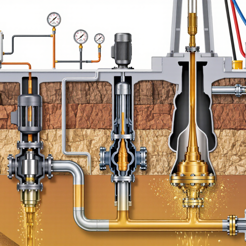
In 2026, downhole jet pumps remain useful where wells produce sand, gas, or highly variable fluids. Their operation is simple in concept. A surface pump sends power fluid down the tubing. The fluid passes through a small nozzle, creating a low-pressure zone. Well fluids enter the mixing chamber, then travel upward through the production tubing.
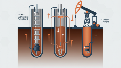
Common configurations include fixed-nozzle, adjustable-nozzle, and reverse-circulation systems. Fixed-nozzle designs offer predictable operation. Adjustable nozzles provide better control when reservoir pressure changes. Reverse circulation can simplify pump recovery, but it may complicate surface separation. Field engineers should check nozzle size, power-fluid rate, tubing pressure, and gas volume together. One reading rarely explains poor performance.
SPE technical literature commonly places hydraulic jet-pump efficiency near 20–35%, depending on pressure ratio, fluid properties, and nozzle condition. That figure is lower than many people expect. The U.S. Energy Information Administration reported continued growth in mature-field production challenges, increasing the value of adaptable artificial-lift systems. API artificial-lift guidance also emphasizes pressure surveillance and controlled operating envelopes. In practice, a cloudy power-fluid sample or a sudden pressure spike may reveal erosion before failure. Models help, but they are not perfect. Real wells often behave differently from design sheets.
Downhole jet pumps have no moving parts in the wellbore. A high-pressure power fluid passes through a nozzle, creates a low-pressure zone that entrains reservoir fluids, and then converts velocity into pressure through a diffuser. The ranges below represent typical engineering design envelopes for surface power-fluid pressure; actual values depend on depth, fluid properties, gas fraction, solids, nozzle geometry, and well productivity.
Conventional forward-flow designs are commonly selected for flexible production operations, reverse-flow designs can simplify certain tubing and annulus arrangements, and casing-flow configurations may be useful when larger flow paths or higher liquid throughput are required. No single type is best for every oil well.
Downhole jet pumps use high-pressure power fluid to lift produced fluids through a nozzle and throat. Their simple design handles sand better than many moving-part pumps.
Fixed jet pumps are installed with the production tubing. They offer stable placement and efficient operation in predictable wells.
Retrievable jet pumps can be recovered through tubing, reducing workover time.
Free pumps travel through the tubing and land in a standing valve. This option can simplify replacement in deep or deviated wells. It is not always trouble-free. Poor seating, debris, or unstable fluid rates may reduce performance.
Reverse-flow jet pumps are useful when the well completion requires a different circulation path. Casing-installed designs can provide larger flow areas, but they demand careful hydraulic planning.
Pump selection should consider depth, gas fraction, produced solids, water cut, and available surface pressure. Field technicians should compare nozzle and throat combinations against actual well tests, not only supplier charts.
A smaller throat may improve velocity, yet it can restrict total liquid volume.
That tradeoff is easy to miss.
Experience also shows that laboratory efficiency rarely matches field efficiency. Temperature, viscosity, gas interference, and erosion change the result.
2026 Best Downhole Jet Pump Types for Oil Wells?
Choosing a jet pump starts with well behavior, not a catalogue label. Hydraulic jet pumps suit wells with sand, high deviation, or limited downhole access. They contain no downhole moving parts. That matters when workover costs are high. Conventional fixed-nozzle pumps are simple and dependable. Adjustable-nozzle designs provide better tuning when reservoir pressure changes. Reverse-flow configurations can simplify circulation and retrieval in selected completions.
Compare performance using production rate, power-fluid demand, pressure loss, and operating stability. SPE technical literature commonly places hydraulic jet-pump efficiency near 10–30%, depending on nozzle geometry and well conditions. That range is wide. It should not become a promise. API RP 11V6 recommends checking injection pressure, fluid properties, and completion geometry before selecting equipment. A practical field check includes sand concentration, gas fraction, tubing size, and expected pump intake pressure.
Well compatibility often decides the result. A jet pump may tolerate solids better than a precision rotating system, yet it needs reliable surface power-fluid equipment. High gas rates can reduce mixing efficiency and increase backpressure. Multiphase calculations are essential. Use measured fluid data whenever possible, because laboratory curves can mislead in viscous crude. A 2024 SPE artificial-lift review also stresses matching pump design with changing inflow, not only initial production. I would compare three cases: startup, peak liquid rate, and late-life decline. The cheapest design may fail in the third case. That is an uncomfortable but useful test.
Selecting a downhole jet pump in 2026 requires more than comparing pressure ratings. The IEA Oil 2024 report projects global oil demand near 105.4 million barrels per day by 2029. That pressure favors dependable artificial-lift systems, especially in mature wells with declining reservoir energy.
Installation starts with fluid compatibility. Engineers should match nozzle and throat geometry to expected rate, water cut, gas volume, and solids loading. The power-fluid line needs pressure testing before the pump reaches depth. A clean completion is essential. Small sand grains can damage surface valves and disturb injection efficiency. Field teams should record setting depth, tubing drift results, fluid density, and baseline pressures. These details often matter more than catalog performance.
Monitoring should track injection pressure, production pressure, casing pressure, temperature, water cut, and produced solids. A sudden pressure rise may indicate a blocked nozzle. Falling production with stable injection pressure may suggest throat wear or reservoir decline. The 2024 SPE Artificial Lift Conference papers repeatedly emphasize surveillance quality and trend analysis, rather than isolated readings. That is practical advice. One reading can mislead. Maintenance normally includes fluid filtration, valve inspection, pressure-test verification, and periodic pump retrieval when performance declines. Jet pumps have no downhole moving parts, but surface equipment still wears. I have seen operators blame the pump too early. Sometimes the real problem is poor fluid cleanliness or an inaccurate gauge.
| Downhole Jet Pump Type | Typical Well Application | Representative Operating Range | Key Installation Requirements | Monitoring Requirements | Maintenance Requirements | Main Limitations and Selection Notes |
|---|---|---|---|---|---|---|
| Conventional Reverse-Flow Jet Pump | Mature oil wells with a retrievable downhole assembly and an existing tubing-and-casing completion. |
Common surface power-fluid pressure: approximately 1,000–3,000 psi. Suitable depth and rate depend on fluid properties, nozzle-throat geometry, and well pressure. |
Run the pump in the tubing or insert it into a compatible pump chamber. Confirm tubing, casing, standing-valve, and seating dimensions. Pressure-test the power-fluid conduit before commissioning. Circulate clean fluid to reduce nozzle plugging risk. | Record injection pressure and rate, production-fluid rate, casing pressure, tubing pressure, fluid level, water cut, and produced-fluid temperature. Compare actual hydraulic performance with the pump design curve. | Inspect the nozzle and throat when efficiency declines. Check for erosion, scale, sand damage, gas interference, and plugged passages. Flush the power-fluid circuit and verify pressure gauges, valves, and flow meters. | Requires adequate power-fluid supply and surface pumping capacity. Efficiency can fall when solids, gas, or highly viscous crude disrupt the jet profile. |
| Free-Pump Retrievable Jet Pump | Wells where the downhole pump should be retrieved through circulation without pulling the production tubing. | Well depth is completion-dependent. Often selected for moderate-to-deep wells where workover reduction is important. | Install a landing nipple or pump chamber with the correct orientation and internal dimensions. Confirm that circulation paths are open and that the pump can pass through the tubing. Use filtered power fluid and verify the retrieval mechanism. | Trend injection pressure, return-fluid pressure, circulation rate, production rate, pump intake pressure, and annulus pressure. A rising pressure at a constant rate may indicate restriction or nozzle fouling. | Retrieve and inspect the pump when output falls, injection pressure rises, or solids production increases. Replace damaged seals, nozzle, or throat components as required. Clean the chamber and confirm smooth landing. | Requires precise completion compatibility. Debris, scale, or poor circulation can prevent retrieval. Not ideal when the power-fluid path cannot be kept clean. |
| Fixed Downhole Jet Pump | Wells with stable operating conditions where frequent pump retrieval is not expected. | Performance is determined by the installed nozzle-throat combination and available power-fluid pressure. | Run the pump as part of the tubing completion. Confirm depth, centralization, seal integrity, and orientation. Perform a pressure test on tubing and annular barriers before opening the well to production. | Continuously or routinely track power-fluid pressure, power-fluid rate, oil rate, water rate, casing pressure, tubing pressure, and fluid level. Watch for changes in hydraulic efficiency and drawdown. | Maintenance usually requires a tubing pull or workover. Schedule well tests and pressure surveys to identify declining performance before a full intervention is required. | Higher intervention cost if the nozzle or throat becomes damaged. Best suited to wells with limited solids, predictable inflow, and relatively stable fluid properties. |
| Insert Jet Pump | Existing wells where the tubing is intended to remain in place during pump replacement or performance changes. | Appropriate operating range varies with the insert chamber, tubing size, and selected nozzle-throat ratio. | Confirm the insert pump dimensions, seating depth, landing profile, and circulation route. Verify wireline or slickline access if applicable. Pressure-test the installation and confirm positive seating before starting injection. | Monitor injection pressure and rate, production rate, annular pressure, tubing pressure, and pump response after each operating change. Conduct periodic fluid-level or downhole-pressure surveys. | Retrieve the insert pump for inspection, cleaning, nozzle replacement, or throat replacement. Check the seating seals and landing surfaces for erosion, scale, or deformation. | Installation depends strongly on completion geometry. A damaged or obstructed chamber can cause leakage, unstable operation, or difficult retrieval. |
| Gas-Handling Jet Pump Configuration | Oil wells with significant free gas at the pump intake, changing gas-oil ratio, or unstable inflow conditions. | Selection depends on gas volume fraction, intake pressure, fluid density, and available power-fluid pressure; no universal rate limit applies. | Place the intake at a suitable depth and evaluate gas breakout, annular flow, and separation behavior. Confirm that the completion can manage gas and that surface separation and back-pressure control are adequate. | Measure gas rate or gas-oil ratio, intake and discharge pressure, power-fluid rate, casing pressure, tubing pressure, liquid rate, and fluid level. Look for surging, gas interference, and declining liquid lift. | Inspect the nozzle and throat for erosion caused by high-velocity multiphase flow. Check separators, chokes, flow meters, and gas-handling equipment. Remove deposits that restrict the power-fluid or production path. | Gas can reduce hydraulic efficiency and make rate interpretation difficult. Proper gas separation, pressure control, and operating stability are essential. |
| Sand- and Solids-Tolerant Jet Pump Configuration | Unconsolidated reservoirs, wells with intermittent sand production, or cleanup operations after stimulation and workover. | The allowable solids loading is design-specific. Abrasive particles can rapidly change nozzle and throat dimensions. | Use an appropriate downhole filter or solids-management design where feasible. Establish a controlled startup sequence and avoid sudden rate changes that can mobilize large quantities of sand. | Track sand concentration or solids indications, differential pressure, injection rate, production rate, vibration, erosion trends, and changes in water cut. Inspect surface strainers and separation equipment frequently. | Clean strainers and desanders, flush the power-fluid system, and inspect nozzle, throat, tubing, and valves for erosion. Replace components when dimensional wear causes a measurable loss of efficiency. | Jet pumps tolerate solids better than many close-clearance lift systems, but they are not immune to abrasion. Erosion can increase power-fluid demand and reduce oil recovery. |
| High-Temperature or Corrosion-Resistant Jet Pump Configuration | Deep, hot, sour, saline, or chemically aggressive oil wells requiring materials compatible with the produced fluids. | Temperature and pressure limits are controlled by metallurgy, elastomers, completion components, and well-control requirements. | Confirm material compatibility with hydrogen sulfide, carbon dioxide, chlorides, scale chemicals, and treatment fluids. Use appropriate pressure-control equipment and follow sour-service and well-integrity procedures. | Monitor temperature, pressure, corrosion indicators, produced-water chemistry, hydrogen sulfide where applicable, injection-fluid quality, and changes in pump efficiency. | Inspect corrosion-prone surfaces, seals, valves, fittings, and flow passages. Maintain chemical-injection systems and replace components according to inspection findings and service-life limits. | Material selection and elastomer compatibility can significantly increase cost and determine service life. Temperature, pressure, and sour-service limits must be verified for the complete system. |

Choosing the best downhole jet pump type in 2026 starts with the well, not a catalog. Review measured depth, tubing size, flowing pressure, and expected production range. A fixed-nozzle design may suit stable wells with predictable conditions. An adjustable-nozzle design offers more control when reservoir pressure or water cut changes. That flexibility can help, but it may add operating complexity. Field experience shows that pumps sized only for peak output often perform poorly during lower-rate periods. Design for the real operating window.
Fluid behavior deserves equal attention. Heavy oil, free gas, sand, and scale can change pump performance quickly. Compare nozzle geometry, throat size, power-fluid pressure, and expected injection rate. Check gas-handling capability before approving the design. Confirm metallurgy against produced water, chlorides, temperature, and chemical treatment. Request traceable test data, clear performance curves, and service records from similar wells. A calculation is useful, but it is not the well. Actual pressure surveys may expose assumptions that looked reasonable on paper. No model is perfect.
Tips: Build a simple operating matrix before selection. Include startup, normal, upset, and decline conditions. Check available surface pressure and water volume. Leave margin for uncertain gas behavior. Monitor intake pressure, power-fluid rate, casing pressure, and produced-fluid changes after installation. Short trials can mislead. Review several weeks of stable data. If sand loading is seasonal, test that condition separately. Involve production, completion, and maintenance personnel before approval.