Why choose a sucker rod pump for an oil well? The answer often begins with a visible motion: a surface unit rocks steadily while a polished rod moves up and down. That movement travels through a string of rods to a downhole pump, lifting produced fluid toward the surface. The design is familiar across many mature oil fields, and its mechanical action is relatively easy to observe. Still, a familiar system is not automatically the right one.
A sucker rod pump can suit wells with established production, accessible surface equipment, and fluid conditions within the system’s operating limits. Operators can monitor indicators such as stroke behavior, pump fillage, fluid level, and changes in produced volume. These details help guide adjustments and maintenance. But performance depends on more than the pump itself. Rod wear, corrosion, gas interference, well deviation, and changing reservoir conditions can all affect reliability. Small warning signs matter.
The practical choice comes from matching the equipment to the well. A suitable design considers depth, expected production rate, fluid properties, power availability, and maintenance access. It also weighs operating costs against alternatives. A sucker rod pump may offer a straightforward, serviceable solution, but it can require regular inspection and careful setup. There is no universal winner. The useful question is not simply whether this pump works, but whether it fits this well—and whether the evidence supports that decision.
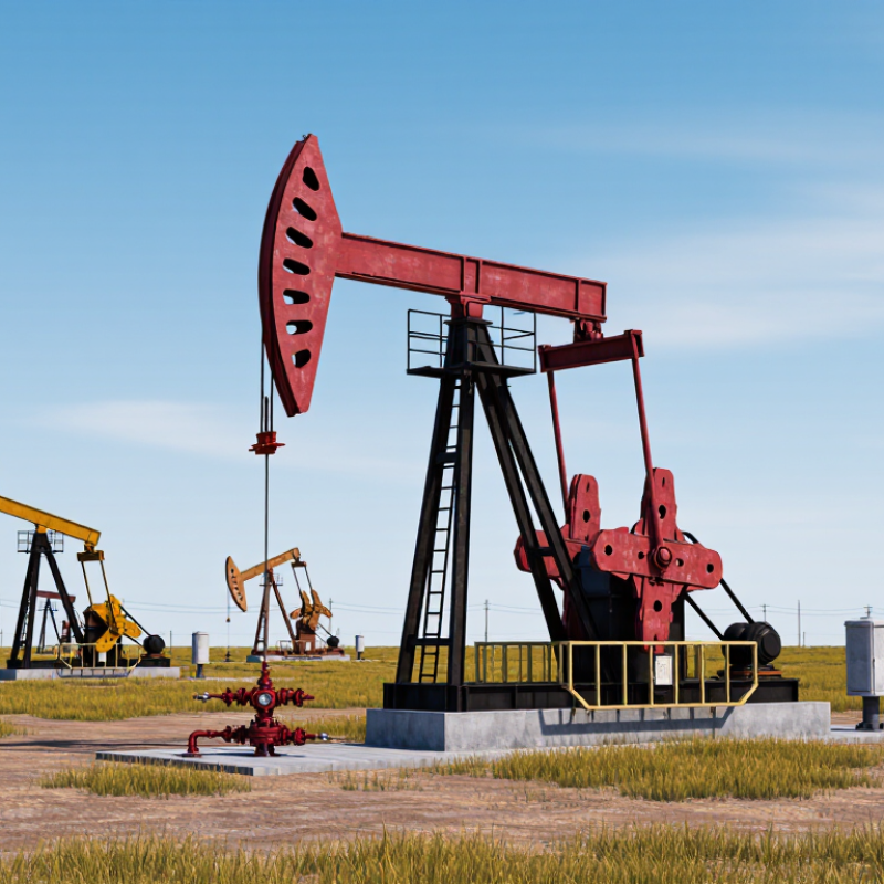
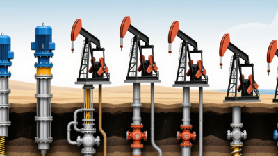
A sucker rod pump transfers motion from the surface to a pump below the fluid level. A motor turns a gearbox, which moves the walking beam up and down. The polished rod follows that movement at the wellhead, while a connected steel rod string carries it downhole. At the bottom, a plunger moves inside a pump barrel. The surface equipment is visible; most of the working parts are not.
During the upstroke, the traveling valve closes and the standing valve opens. Reservoir fluid enters the pump barrel. On the downstroke, the standing valve closes, while the traveling valve opens to let fluid pass above the plunger. Repeated strokes move that fluid upward through the tubing. The cycle repeats. A simplified diagram makes this look effortless, but rod stretch and changing fluid conditions can complicate the motion.
Pump performance depends on more than stroke length. Gas in the fluid, high viscosity, worn valves, or rod friction can reduce the amount lifted. Field checks may include fluid level, polished-rod load, and unusual vibration near the beam or wellhead. A load trace can help identify changes, but it does not explain every problem by itself. That part is easy to overlook.
Where Rod Lift Fits: Well Depth, Fluid Rate, and Operating Conditions
A sucker rod pump can suit wells where steady, moderate fluid production matters more than very high output. Its surface drive moves a rod string, which operates a downhole pump. The arrangement is familiar to many production teams, and technicians can often inspect key components without specialized intervention equipment. That matters. Still, depth alone does not determine whether rod lift is a good fit. Rod stretch, tubing friction, and well deviation can affect performance, especially in deeper or crooked wells.
Fluid rate and operating conditions deserve equal attention. Rod lift can handle changing production, but excessive gas, abrasive sand, or heavy fluid may reduce pump efficiency and increase wear. A well producing a few barrels per day has different needs from one with a much larger inflow. Engineers typically compare expected rate, fluid level, pump size, rod loading, and available power. They also consider access for maintenance. A design that looks efficient on paper may prove awkward when the well is remote or parts are difficult to reach.
Tips: Check the fluid level and production trend before selecting pump capacity. Watch for rising vibration, polished-rod wear, or frequent downtime; each can signal a mismatch or developing fault. Review actual operating data after installation. Models simplify things, sometimes too much. Revisit assumptions when water cut, gas, or sand production changes.
Why Choose a Sucker Rod Pump for Oil Wells?
API 11AX pumps and API 11B rods give operators a shared basis for equipment selection. API 11AX standardizes key dimensions and requirements for subsurface sucker rod pumps. API 11B covers sucker rods and related components, helping define dimensions, connections, and material requirements. This common language makes it easier to check whether parts are compatible before they reach the wellsite.
Fit matters. A pump’s size and configuration must suit the tubing and operating conditions. Rod selection also depends on load, corrosion exposure, and the well’s depth and deviation. For example, a rod string moving through a deviated section may experience more wear than one in a straight well. Standards help narrow choices, but they do not replace a review of actual well data.
In field work, technicians still need to confirm markings, connection types, and condition during inspection. A standardized component is not automatically the right component. Nor does compliance guarantee a long service life. It can be tempting to treat a specification sheet as the whole answer; that shortcut deserves a second look. Pressure, fluid properties, operating speed, and maintenance practices all affect performance.
| Selection Dimension | What the Standards Address | Practical Selection Consideration | Why It Matters in the Well |
|---|---|---|---|
| Artificial-lift method | A sucker rod pumping system uses surface reciprocating equipment to move a rod string and operate a downhole reciprocating pump. | Consider it when the well’s production target, fluid properties, depth, and operating conditions suit reciprocating lift. | It provides a direct, adjustable way to lift produced fluid, but it is not the best fit for every well or production rate. |
| Subsurface pump specification | API Specification 11AX covers subsurface sucker rod pumps and related fittings, including standardized pump designs and dimensional requirements within its scope. | Match pump type and size to the tubing or insert arrangement, well configuration, expected fluid volume, and applicable standard edition. | Consistent specifications help operators compare and select compatible equipment; they do not replace well-specific engineering. |
| Rod string specification | API Specification 11B covers sucker rods, pony rods, polished rods, and related couplings and accessories within its scope. | Select rod dimensions and material grade for the anticipated tensile loading, operating environment, and connection requirements. | A correctly selected rod string transmits the surface motion to the pump while helping manage cyclic loads and fatigue risk. |
| Equipment compatibility | Standardized designations and dimensions support equipment identification and compatibility checks for components made to the relevant requirements. | Verify the pump, rods, couplings, and well tubulars as a complete configuration; confirm dimensions and connections rather than relying on a standard number alone. | API conformity does not mean that every pump or rod is interchangeable across all sizes, designs, or service conditions. |
| Well depth and loading | The standards define equipment requirements; the actual load calculation depends on the well and the selected operating setup. | Evaluate rod-string weight, fluid load, pump depth, stroke, speed, and expected dynamic loads during system design. | These factors influence rod stress, pump performance, and the likelihood of mechanical failures. |
| Fluid and gas conditions | API equipment standards do not determine whether a well’s fluid or gas conditions are suitable for a particular pump configuration. | Assess gas production, viscosity, solids, corrosive constituents, and fluid level when selecting pump configuration and materials. | Free gas, abrasive solids, or corrosive fluids can reduce pump efficiency or increase wear and maintenance needs. |
| Operating adjustment | The standards support consistent equipment specification; operating settings are determined by the application. | Set and monitor stroke length and pumping speed in line with the well’s inflow, equipment limits, and production objectives. | Appropriate operation can help balance production with mechanical loading and reduce unnecessary wear. |
| Inspection and maintenance | Applicable API requirements provide a common basis for equipment specifications and quality-related checks. | Use documented inspection, installation, and maintenance procedures, and check the specific standard edition required for the project. | Consistent records and checks support safer installation, equipment tracking, and more reliable replacement decisions. |
Selection note: API 11AX and API 11B help standardize equipment specifications, but final pump and rod selection should be based on well data, engineering calculations, operating conditions, and the applicable editions of the standards.
A sucker rod pump suits many oil wells because its reciprocating motion can be adjusted to match changing production conditions. Its theoretical output depends on three linked settings: plunger diameter, downhole stroke length, and strokes per minute. Small changes matter.
The plunger diameter has a squared effect on displacement. A larger diameter increases the swept area, calculated as π times diameter squared divided by four. Each stroke then moves that area multiplied by the downhole stroke length. Multiply this volume by strokes per minute and operating minutes to estimate theoretical daily output. With inches as the units, divide the daily cubic-inch total by about 9,702 to convert it to barrels.
Speed adds cycles, but faster is not always better. If the pump cannot refill fully between strokes, actual production may fall short of the calculation. Gas, fluid viscosity, and pump wear can also reduce fillage. And surface stroke is not downhole stroke: rod stretch and tubing movement can change the distance the plunger travels. The estimate is useful, but it is only a starting point. Compare it with measured production and pump-card data; field readings can be messy, and that is worth acknowledging.
A sucker rod pump keeps many routine inspection points at the surface. Technicians can check the polished rod, stuffing box, belts, guards, and control panel without opening the well. During a walkaround, they can listen for changes in stroke rhythm, spot oil seepage, and check for loose fasteners. The U.S. Energy Information Administration reported average U.S. crude oil production of 12.9 million barrels per day in 2023. That figure does not measure pump reliability, but it shows why repeatable field checks matter across busy operations.
Accessible equipment also makes condition tracking simpler. Record normal belt tension, motor temperature, and vibration readings, then compare them during later visits. Follow site procedures and equipment manuals; easy access is not permission to work on energized machinery. A reachable panel can create false confidence. Surface checks cannot reveal every downhole problem, and rushed inspections may miss small leaks.